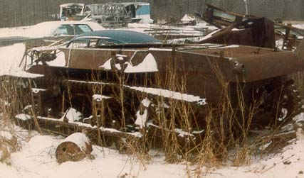
Figure 1
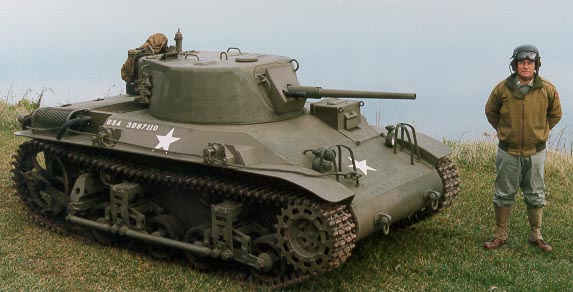
Figure 2
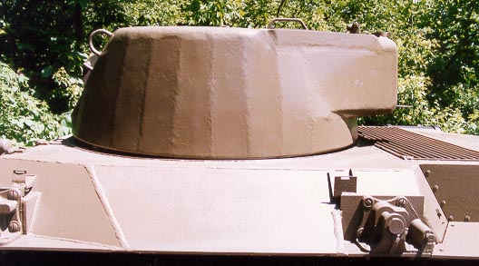
M22 Locust (serial number 110) was found in a farmer's field in the midwest as shown in Figure 1. Only 830 of these tanks were manufactured. Scuttlebutt tends to indicate that these tanks were sold to the public, minus the turret, after the war. Consequently, several hulls have been reclaimed throughout the midwest by military vehicle collectors. Hull number 110 has been restored to operating condition despite the poor condition of the vehicle and absence of many critical parts. Figure 2 is the final result of the restoration process which includes a completely mobile vehicle, turret, simulated cannon and machine gun fire. This article is a review of the restoration process and the problems/solutions encountered.
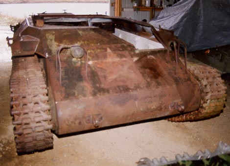
Luckily the vehicle still rolled, thereby making it relatively easy to load on a tilt bed vehicle carrier. Figure 3 shows the vehicle in a work shed ready for the restoration to commence. There was no turret or gun available and the front armor had been torched for easy access by the driver. The engine did not run but did turn and could be made operable.
The first step in such a restoration is to define the goal or end result. In this case it was decided to restore the vehicle such that the outward appearance would be nearly identical to that of the original and that the vehicle be fully operable so that it could be used in WWII reenactments.
The hull was cleaned, derusted and painted. The frontal armor was repaired as shown in Figure 4. Steel fenders were manufactured and installed that matched the early production T9E1 vehicle. A standard tow cable and set of lights were added and the siren rebuilt. Figure 5 shows the Stuart Engine (346 V8) and transmission being mounted on a specially designed engine mount that bolted to the hull through existing holes. A screw on cartridge oil filter was adapted to the engine to save room. The cooling system utilized a large van radiator that was mounted over the transmission housing in a manner similar to that of the M24 Chaffe light tank that used the same engine. The generator was abandoned and replaced with an alternator in order to provide sufficient amperage to drive the electrical cooling fans mounted on the radiator. The engine mount was designed such that the oil pan was less than an inch off of the floor, since this is a very tight fit under the rather low bustle. The distributor shaft was shortened in order to fit the engine as shown in Figure 5. A heat shield was manufactured to reduce heat transfer from the exhaust to the fuel tank which sits adjacent to the engine on the left side. The Cadillac 346 V8 has a good driveability reputation in that it starts and runs well. Ignition and replacement parts are easily available. On the flip side, the engine and transmission are heavy with relatively low horsepower output (roughly about 100 HP). So vehicle performance was expected to decrease when replacing an 800 lb., 160 HP engine with a 1300 lb., 100 HP engine. Nevertheless, the enhanced reliability/driveability outweighed the reduced vehicular performance.
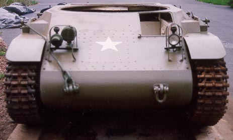
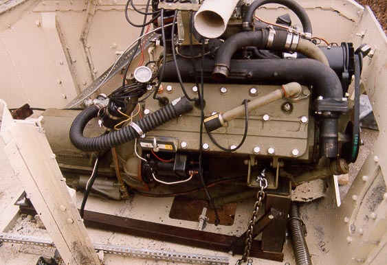
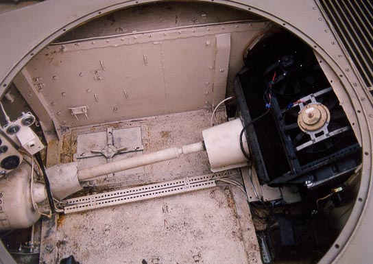
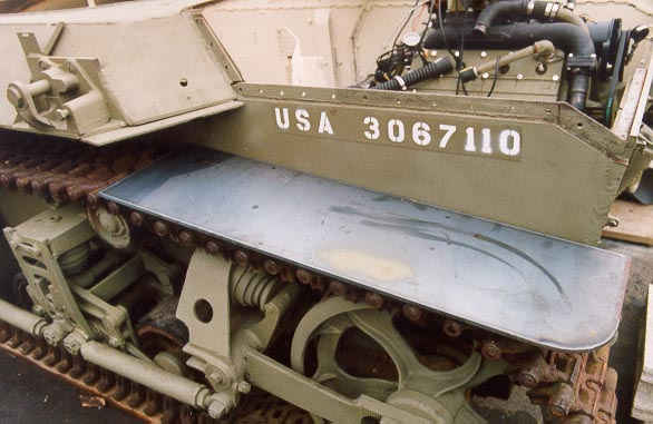
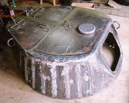
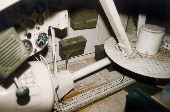
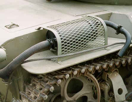
Figure 10 shows the inside of the tank with a simple turret basket and skip ring used to transfer power to the winch , radios and simulated fire guns. Figure 11 shows the exhaust system and heat guard that were fabricated after review of photographs. The exhaust pipe originally pointed away from the right side of the vehicle. This was uncomfortable for reenactors during reenactments since the exhaust would be directed at them. Consequently another 90 degree elbow was added to direct the exhaust downward. The rubber road wheels had deteriorated and were remolded with polyurethane which allowed easy movement of the vehicle on the steel track. Fractured track link guides were built back up by welding. An aluminum motor boat fuel tank was fitted with the appropriate grounding and venting. A shop vacuum filter was adapted as a dry element air filter. The older style driver hatch (see Figure 2) was fabricated for more room and visibility. The driver hatch was designed to open fully for emergency exit. The original did not allow exit and the driver had to exit out the turret. The vehicle was restored over a period of 10 months.
Overall performance of the vehicle was reasonable as speeds of 20 MPH were easily achievable. However the noise level inside the vehicle with the exposed drive train and metal tracks is sufficiently frightening to preclude speeds in excess of 20 MPH. The vehicle appears reasonably authentic from the outside and is very reliable. It has participated in several displays and reenactments. The fact that several vehicle collectors have inquired as to the source for purchasing the turret attests to its authentic look.
 BACK TO ROBERTS ARMORY HOME PAGE